 Creating slab components
|
Tool |
Tool set |
|
Slab
|
Building Shell |

Slab components define the sections that make up a slab. For example, to indicate that a slab is made up of gypsum board ceiling, wood framing, and a plywood deck, define a component for each of these items to illustrate their location. Slab components can be offset from the edges of the walls (automatically bounded edges) or the edge of the slab (manual edges); each edge can have a unique offset setting, as needed. Components’ appearance can be specified for cross-section views, and they can be textured, creating realistic section views and rendered views, as well as accurate slab supply estimates. If a material resource is used to define a component, the material typically provides the fill, texture, physical attributes, and construction information needed for drawings, renderings, and reports. The area and volume of slab components (minus any holes cut) can be calculated in worksheets; see Worksheet functions).
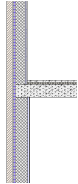
The overall thickness of a slab is equal to the sum of its components. Component fill and pen style are only displayed in section viewports.
The Auto-display detail levels for design layers preference can be used to show or hide slab components based on scale; see Hiding slab components.
Use the Eyedropper tool to copy slab component settings from one slab to another (see Transferring attributes).
To define a slab component:
Do one of the following:
To define a component while a slab or slab style is being created, open the Definition tab of the Slab Preferences dialog box.
To define or edit slab components for an existing, unstyled slab, select the slab and click Components on the Object Info palette to open the Slab Components dialog box.
For a description of the parameters in the Slab Preferences dialog box or the Slab Components dialog box, see Slab preferences.
Below the Components list, click New to create a new component or select a component to edit and click Edit.
The Slab Component Settings dialog box opens. Specify the component thickness, name, and parameters.
Click to show/hide the parameters.Click to show/hide the parameters.
|
Parameter |
Description |
|
Definition |
|
|
Name |
Provide a name for the component, which displays in the Components list in the Slab Preferences dialog box |
|
Function |
Specifies a function for the component, to be included in IFC exports |
|
Class |
To control appearance and visibility, select a class from the list of classes present in the drawing, or create a new class. Select <Object Class> to place the component attributes in the same class as the slab object. |
|
Use material |
Uses a material resource for this component; select a material from the Resource Selector. The Lambda, Section Fill, and Texture settings are set to the material’s settings, and the Lambda and Section Fill parameters are disabled. |
|
Lambda |
Indicates the lambda value for the slab component. The lambda value participates in energy analysis calculation parameters for the slab component. Vectorworks Architect is required to conduct an energy analysis; however, energy-related parameters can be specified here for informational purposes. |
|
Look Up |
Opens the Look Up Lambda Value dialog box, to specify the lambda value. The value can be calculated based on the U-value or R-value and the component thickness; the calculated value is displayed. Alternatively, lambda values are provided for typical component elements; select the component element with its predefined lambda value. Filter the displayed list by entering a filter term; click Edit List to enter the value manually. |
|
Thickness |
Specifies the component’s thickness; the thickness of a slab is the sum of its components. A component must have a thickness greater than 0. |
|
Edge Offset |
The method of offsetting the component from the edge of the slab depends on whether the edges are automatically bounded with walls or drawn manually. The settings on this dialog box establish the default offsets for new slabs and edges. The offsets for existing edges can be edited individually by Setting edge offsets. The edge offset setting displays for each component in the component list on the Definition tab of the Slab Preferences dialog box. |
|
Auto-Bound |
Sets the component edge to the inner or outer face of the wall, outer face of the inner wall component, inner face of the outer wall component, or inner face/outer face/center of the wall component designated as the core component. Set the component’s additional Offset amount, if any. |
|
Manual |
Specifies the offset of the component from the edge of the slab |
|
Master Snap Points |
Sets the location of any master snap points for the component. A master snap point takes priority over other object snap points; add master snap points to the top or bottom of components where priority snapping is desirable. For example, when dimensioning slabs, you may wish to easily place the dimension witness line on the top of a specific component. See Concept: Snapping indicators. |
|
Top of component/ Bottom of component |
Select the option to enable a master snap point location on either the top or bottom, or on both the top and bottom of the component |
|
Section Fill |
Specifies the component appearance in section views. If the component uses a material, the fill is set to the material’s fill, and the controls are disabled. Otherwise, select a fill style, or Class Style to set the fill attributes by class. Depending on the Style selected, select a color, pattern, or resource (hatch, image, gradient, tile). Use a tile fill with Fit to Wall selected to represent insulation fill. See Defining and editing tiles. |
|
Section Pen |
Specifies the component appearance in section views. Select a pen style, or Class Style to set pen attributes by class. Depending on the Style selected, select a color, pattern, or line type resource. |
|
Thickness |
Select the line thickness; to use a custom thickness, select Set Thickness from the line thickness list (see Line thickness attributes) |
|
Texture |
Applies the selected texture to the component. If the component uses a material, the texture is initially set to the material’s texture, but this can be overridden. Class Texture sets the component to use the texture specified by the component’s class; see Concept: Applying textures by class. If Texture is chosen, this setting overrides the object material and/or class texture; select a texture from the Resource Selector. The Object Info palette Render tab has additional texturing controls for existing objects; see Managing object textures from the Object Info palette and Textures on objects with components. Textures applied from the Object Info palette override the textures set here unless the texture is set by style. |
|
Make All Attributes By Class |
Sets all fill, pen, and texture attributes by class, except those that come from a material |
|
Remove By Class Settings |
Removes all class settings for fill, pen, and texture attributes; does not affect material definitions with attributes set by class |
After you click OK, the slab’s Overall Thickness value changes to be determined by its components. As components are defined, they display in the preview. Click and drag a component in the # column to change its order. Determine which component is the datum component by clicking in the Datum column. Set the datum to the top or bottom of the component.
